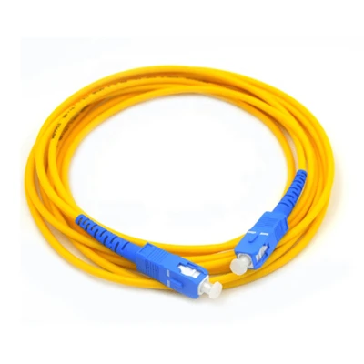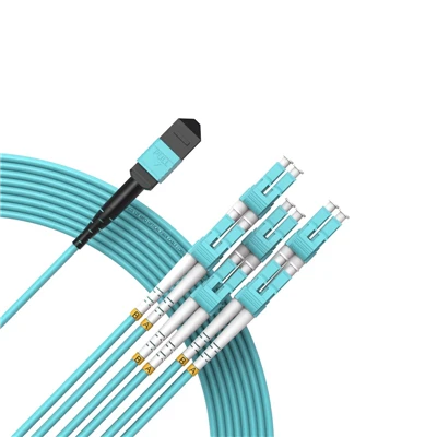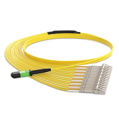

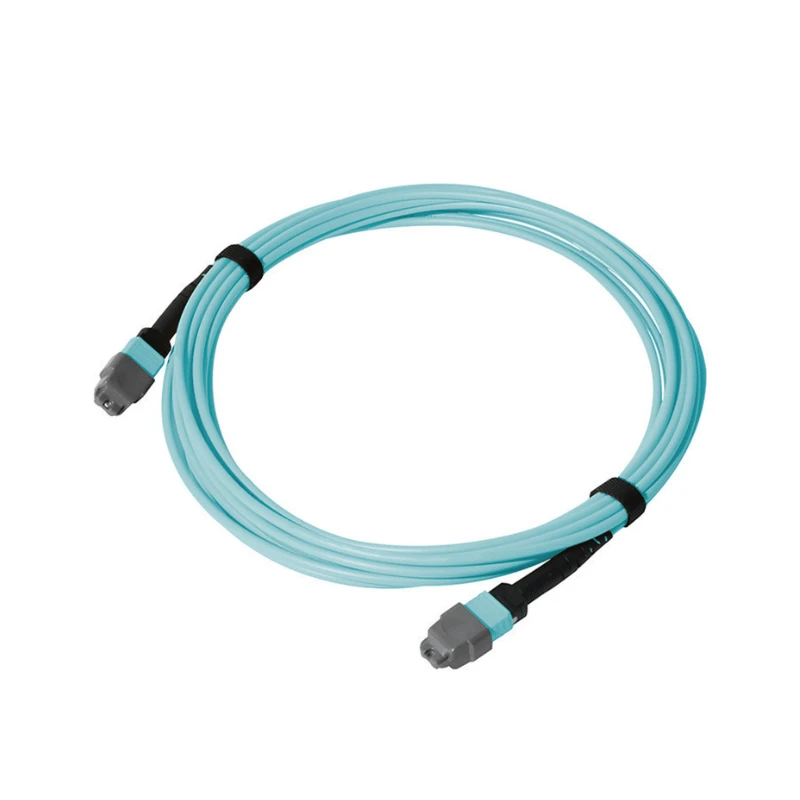
The OS2 MTP Single Mode Fiber Cable is a factory-terminated MTP/MPO trunk assembly using OS2 9/125 μm single-mode fiber, with multi-fiber connectors at both ends for direct connection between compatible MTP/MPO interfaces.
Technical Specifications
|
Parameter |
Specification |
|
Product Type |
OS2 MTP Single Mode Fiber Cable |
|
Fiber Type |
OS2 Single Mode, 9/125 μm |
|
Fiber Grade |
G.652D / G.657A1 |
|
Fiber Count |
8 / 12 / 24 / 48 Fibers |
|
Assembly Type |
MTP/MPO Trunk Cable |
|
Polish Type |
APC / UPC |
|
Polarity |
Type A / Type B / Type C |
|
Standard Insertion Loss |
≤0.35 dB |
|
Low-Loss Insertion Loss |
≤0.20 dB |
|
Return Loss |
≥50 dB (APC) |
|
Operating Temperature |
-20°C to +70°C |
|
Optical Testing |
Insertion Loss and Return Loss |
|
Test Documentation |
Test data provided with shipment |
|
Connector Standard |
IEC 61754-7 |
|
Environmental Compliance |
RoHS |
|
Custom Configuration |
Custom length, fiber count and labeling |
MTP Configuration: Gender, Polish and Polarity
MTP/MPO configuration should be matched to the mating interface and fiber mapping of the target system.
Polish Type: Confirm APC or UPC according to the connected equipment, cassette, adapter or other mating component.
Polarity: Select Type A, Type B or Type C according to the fiber mapping of the existing cabling system.
For replacement or project orders, an existing cable specification or MTP/MPO connection diagram can be used to verify the required configuration before production.
Standard-Loss vs. Low-Loss
|
Selection Factor |
Standard-Loss |
Low-Loss |
|
Link Budget |
Use when the calculated channel loss remains within the available margin |
Use when the calculated channel loss leaves limited margin |
|
Assembly IL |
≤0.35 dB |
≤0.20 dB |
|
Channel Design |
Suitable where the specified assembly loss fits the complete link budget |
Consider where lower assembly loss is required to maintain the link margin |
|
RFQ Requirement |
Specify the maximum allowable insertion loss |
Specify the maximum allowable insertion loss |
The required loss grade should be determined from the total optical link budget, including fiber attenuation and losses from connectors, cassettes, adapters and other passive components.
Custom Specification
Cable Length
Finished cable length can be specified according to the required connection distance.
01
Fiber Count
Fiber count can be defined according to the required fiber channels or existing cable configuration.
02
Identification
Cable identification and labeling requirements can be specified for project orders.
03
Configuration Review
Buyers can provide an existing cable drawing, MTP/MPO connection diagram, equipment interface specification or purchase specification for review before production.
04
Replacement Orders
Existing cable specifications can be used to verify the replacement assembly against the installed MTP/MPO configuration.
05
Manufacturing Capability
Factory Production: DIMI manufactures factory-terminated fiber optic assemblies using automated cable cutting, stripping and termination equipment.
Production Capacity: Automated assembly equipment is capable of processing more than 10,000 fiber optic assemblies per day, supporting volume and project-based orders.
Quality Management: DIMI maintains ISO 9001:2015 and TL-9000 certifications for its quality management system.
Quality Verification
Production Reference
Each order is manufactured against the confirmed product specification and approved configuration, providing a defined reference for final inspection.
End-Face Inspection
Connector end faces are inspected before shipment to identify contamination, scratches or other visible defects.
Optical Testing
Finished assemblies are tested for insertion loss and return loss before shipment.
Polarity Verification
Fiber mapping is checked against the specified polarity configuration before shipment.
Test Records
The corresponding test data is supplied with the shipment for order verification.
Workmanship Warranty
A 5-year workmanship warranty applies to the product.
FAQ
Q: What is the difference between OS2 and OM4 MTP fiber cables?
A: OS2 uses 9/125 μm single-mode fiber, while OM4 uses multimode fiber. OS2 is specified for single-mode optical links, while OM4 is used in multimode systems. The fiber type should match the transceiver and optical architecture of the network.
Q: What is the difference between MTP and MPO fiber cables?
A: MPO is the standardized multi-fiber connector interface, while MTP® is a specific connector product from US Conec. For procurement, the connector specification and mating interface should be confirmed according to the equipment and cabling system.
Q: What is the difference between an MTP trunk cable and an MTP breakout cable?
A: An MTP trunk cable maintains multi-fiber MTP/MPO connections at both ends. An MTP breakout cable converts the multi-fiber connection into individual connectors such as LC. The required cable type depends on the port architecture of the connected equipment.
Q: Can OS2 MTP cables be connected directly to LC or SC equipment?
A: No. MTP/MPO connectors do not directly mate with LC or SC ports. An MTP-to-LC, MTP-to-SC or other specified conversion assembly is required when the equipment uses these interfaces.
Q: What is the maximum transmission distance of OS2 fiber?
A: OS2 does not have one universal transmission-distance limit. The achievable distance depends on the transceiver, data rate, wavelength, fiber attenuation, connector losses and total optical link budget. The required distance should therefore be checked against the complete link specification.
Q: What is the difference between G.652D and G.657A1 single-mode fiber?
A: G.652D is a conventional single-mode fiber specification, while G.657A1 provides improved bend performance for routing where tighter fiber bends may occur. The required grade should follow the project's fiber specification and installation requirements.
Q: Why does MTP connector keying matter in an MTP/MPO cable assembly?
A: MTP/MPO connector keying controls the physical orientation of the connector during mating. The keying arrangement should match the mating adapter or equipment interface, while fiber polarity should be specified separately according to the required fiber mapping.
Q: What does the MTP connector gender indicate?
A: MTP/MPO gender refers to whether the connector has guide pins. Male connectors have guide pins, while female connectors have guide-pin holes. The required gender should match the mating connector or equipment interface specified for the link.
Hot Tags: os2 MTP single mode fiber cable, China os2 MTP single mode fiber cable manufacturers, suppliers, factory