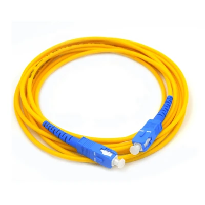


MPO to LC Adapter Cable is a factory-terminated multi-fiber cable assembly that connects a high-density MPO/MTP interface to individual LC duplex ports. It is used to transition between parallel-fiber or high-density MPO infrastructure and equipment, patch panels, or distribution systems using LC interfaces.
Configuration Options
The cable can be configured for different network architectures and installation requirements:
|
Fiber type |
OS2 single-mode; OM3, OM4, or OM5 multimode |
|
Fiber count |
8, 12, and 24 fibers as standard configurations; higher counts available for customized assemblies |
|
MPO interface |
MPO/MTP-compatible, with pinned or non-pinned versions |
|
LC interface |
LC duplex or LC Uniboot |
|
LC polish |
UPC or APC according to fiber type and equipment requirements |
|
Cable construction |
Round cable or breakout/fanout construction |
|
Jacket |
PVC, LSZH, OFNR, OFNP, or applicable CPR-rated constructions |
|
Cable and leg length |
Specified according to rack layout and equipment port spacing |
MPO Polarity & Mating Configuration
MPO polarity and mating configuration must be specified according to the complete optical link, not the cable alone. Type A, Type B, and Type C polarity schemes define different fiber-position mappings between the MPO interfaces, while MPO male/female selection determines whether the connector can physically mate with the corresponding interface.
For ordering, the required configuration should therefore specify:
MPO polarity: Type A, Type B, or Type C
MPO gender: Male (pinned) or female (non-pinned)
Fiber mapping: According to the transceiver, cassette, trunk, or patch-panel architecture
LC channel assignment: Corresponding to the required duplex port sequence
For parallel-optics applications, the polarity and fiber mapping should be verified against the transceiver and the other components in the link before production.
Applications
Data center interconnection
Connecting high-density MPO infrastructure with LC-based switches and patch panels.
01
Transceiver breakout
Distributing multi-fiber MPO interfaces into individual LC duplex channels.
02
MDA/EDA cabling
Connecting backbone or trunk systems to equipment-side LC interfaces.
03
Telecom and ODF systems
Transitioning multi-fiber backbone cabling to individual optical ports.
04
Network upgrades
Integrating existing LC equipment with newer high-density MPO cabling infrastructure.
05
The required fiber type, polarity, and connector gender should be matched to the transceiver and patching architecture before deployment.
Customization & OEM
For distributors, system integrators, and network contractors, the assembly can be customized by fiber count, fiber type, MPO gender, polarity, LC connector type, cable diameter, jacket material, cable length, LC leg length, breakout arrangement, and labeling.
OEM production can also support customer-specified connector brands or components, private labels, barcodes, serialized identification, and project-specific test documentation. For volume orders, the final configuration should be confirmed from the customer's equipment interfaces, polarity scheme, and cabling layout before production.
Testing & Quality Control
Each assembly should be inspected and tested before shipment to verify both connector quality and optical performance.
Typical quality-control procedures include:
Insertion loss and return loss testing for each optical channel
MPO/LC end-face inspection to identify contamination, scratches, or surface defects
3D interferometer inspection of MPO connector geometry where applicable
Fiber continuity and polarity verification
Connector and cable visual inspection
Individual test reports available according to order requirements
Standard-loss (≤0.70 dB) and low-loss (≤0.35 dB) configurations can be specified according to the link loss budget.
FAQ
Q: Can you provide samples before a bulk order?
A: Yes. Samples can be produced for configuration and compatibility verification before volume production.
Q: What information is required to confirm MPO compatibility?
A: We should confirm the MPO connector type, pin configuration, polarity, fiber count, and mating equipment or cassette interface. Providing the equipment model, existing trunk specification, or a cabling diagram is recommended when the required configuration is project-specific.
Q: What is the typical production lead time?
A: Custom batch configurations generally ship within 7–12 business days after specification and order details are confirmed. Expedited production slots are available for qualified project tenders, subject to production capacity and project requirements.
Q: What payment terms are available?
A: Common payment terms include T/T, L/C, PayPal, and credit card. For regular commercial orders, the specific payment arrangement can be confirmed according to order value, customer requirements, and company policy.
Q: How are MPO to LC adapter cables packaged for international shipment?
A: Assemblies are normally individually protected against dust, moisture, bending, and connector damage, then packed in cartons suitable for international transportation. Bulk orders can use additional inner separation or reinforced cartons when required by the shipment quantity and destination.
Q: Can you provide documentation with the shipment?
A: Standard commercial documentation can include the commercial invoice, packing list, and product specification. Test reports, inspection records, labeling lists, and other project documentation can be supplied when required and agreed before shipment.
Q: How should MPO to LC cables be stored before installation?
A: Store the assemblies in a clean, dry indoor environment, protected from excessive dust, moisture, direct sunlight, and mechanical stress. Connector dust caps should remain installed until the cables are ready for connection, and the cable should not be stored with tight bends or excessive tension.
Hot Tags: MPO to lc adapter cable, China MPO to lc adapter cable manufacturers, suppliers, factory