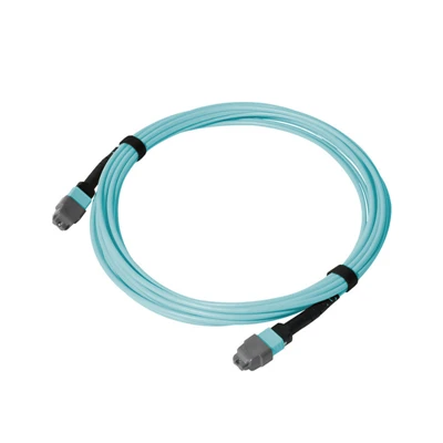


The MPO Multimode Loopback Cable is a factory-terminated optical assembly that routes transmitted signals back to designated receive channels through an MPO interface for local testing of compatible multimode transceivers, ports, and optical equipment.
Technical Specifications
|
Parameter |
Specification |
|
Product Type |
MPO Multimode Loopback Cable |
|
Connector Type |
MPO |
|
Connector Gender |
Male with guide pins / Female without guide pins |
|
Fiber Type |
OM3 / OM4 / OM5 Multimode |
|
Fiber Count |
8 / 12 / 24 fibers |
|
Polarity / Pin Mapping |
Type A / Type B / Type C / Custom Mapping |
|
Connector Polish |
PC |
|
Insertion Loss |
Standard Grade: ≤ 0.70 dB; Elite Low-Loss Grade: ≤ 0.35 dB |
|
Return Loss |
≥ 20 dB |
|
Operating Wavelength |
850 nm / 1300 nm |
|
Jacket Material |
LSZH / PVC / OFNP |
|
Jacket Color |
Aqua / Violet / Lime Green / Custom |
|
Cable Length |
Customized |
|
Operating Temperature |
-20°C to +70°C |
|
Storage Temperature |
-40°C to +85°C |
|
Mating Durability |
≥ 500 cycles |
|
Compliance |
IEC 61754-7, TIA-604-5, RoHS, REACH |
MPO Loopback Configuration
The internal fiber mapping determines which transmitted channels are returned to the corresponding receive channels.
Standard Polarity: Type A, Type B, and Type C configurations are available for setups that use these standard MPO channel arrangements.
Equipment-Specific Mapping: Custom Tx-to-Rx mapping can be manufactured for equipment-specific interfaces, including confirmed QSFP, QSFP28, and QSFP-DD configurations.
Fiber and Connector Configuration
The MPO interface must be matched to the optical and mechanical requirements of the equipment under test.
Interface matching: Confirm the mating MPO interface before ordering.
Connector compatibility: Verify connector gender and guide-pin configuration against the equipment port.
Fiber selection: Select the fiber configuration according to the optical interface being tested.
Configuration reference: For equipment-specific assemblies, the target transceiver specification or equipment documentation can be used as the configuration reference.
Optical Performance Verification
Optical testing
Insertion loss and return loss are measured using EXFO/JDSU equipment and checked against the specified limits.
01
Connector geometry
A 3D interferometer checks fiber height, radius of curvature, and apex offset.
02
End-face inspection
A digital microscope checks for contamination and visible physical defects.
03
Continuity and mapping
Fiber continuity and channel polarity are verified against the approved configuration, including the confirmed Tx-to-Rx mapping for custom assemblies.
04
Quality system
MPO assemblies are manufactured under DIMI's ISO 9001:2015 quality management system.
05
Testing Scenarios
The loopback configuration determines the optical return condition required by the test.
Transceiver verification
Provides a local return condition for checking MPO-based multimode transceiver interfaces.
Port diagnostics
Isolates the optical interface under test without requiring a remote fiber connection.
Production testing
Provides a repeatable optical configuration for controlled equipment verification.
Engineering and burn-in
Allows the same defined interface condition to be reproduced across repeated test procedures.
Manufacturing Process
Manufacturing Capability: DIMI manufactures fiber optic cable assemblies in-house for engineering samples and volume production.
Engineering Review: Non-standard mapping is reviewed against the supplied pinout, wiring schematic, or equipment specification before production.
Production Control: The confirmed specification defines the configuration, mapping, optical requirements, identification, and packaging.
Verification & Documentation: Completed assemblies are inspected and tested before shipment, with test documentation provided according to the confirmed order requirements.
Order Requirements
Order & Lead Time: Flexible quantities are available; standard configurations typically require 3–7 working days, with custom schedules confirmed by configuration and quantity.
RFQ Information: For quotation, provide fiber type, fiber count, connector gender, loopback mapping, cable length, and estimated quantity.
FAQ
Q: What is an MPO multimode loopback cable used for?
A: It creates a local optical return path between designated Tx and Rx channels for testing compatible multimode transceivers, MPO ports, and optical equipment.
Q: How do I choose the correct MPO loopback polarity?
A: Select Type A, Type B, Type C, or custom mapping according to the required Tx-to-Rx channel relationship of the equipment under test.
Q: Can you make a custom MPO loopback for QSFP, QSFP28, or QSFP-DD?
A: Yes. Custom Tx-to-Rx mapping can be manufactured from the equipment pinout, wiring schematic, or confirmed channel-mapping specification.
Q: What is the difference between an MPO loopback and an MPO patch cord?
A: An MPO patch cord connects separate optical interfaces, while an MPO loopback returns designated Tx channels to Rx channels within the local test setup.
Q: How do I choose male or female MPO for a loopback cable?
A: Match the connector gender and guide-pin configuration to the mating MPO interface of the transceiver, test fixture, or equipment.
Q: How do I choose OM3, OM4, or OM5 for an MPO loopback?
A: Select the multimode fiber type specified for the transceiver or equipment being tested to maintain interface compatibility.
Q: What is return loss in an MPO loopback cable?
A: Return loss indicates the optical power reflected back toward the source. The specified return loss is ≥20 dB.
Q: Can an MPO multimode loopback be tested before volume production?
A: Yes. Engineering samples can be produced for interface and channel-mapping verification before volume production when required.
Hot Tags: MPO multimode loopback cable, China MPO multimode loopback cable manufacturers, suppliers, factory