


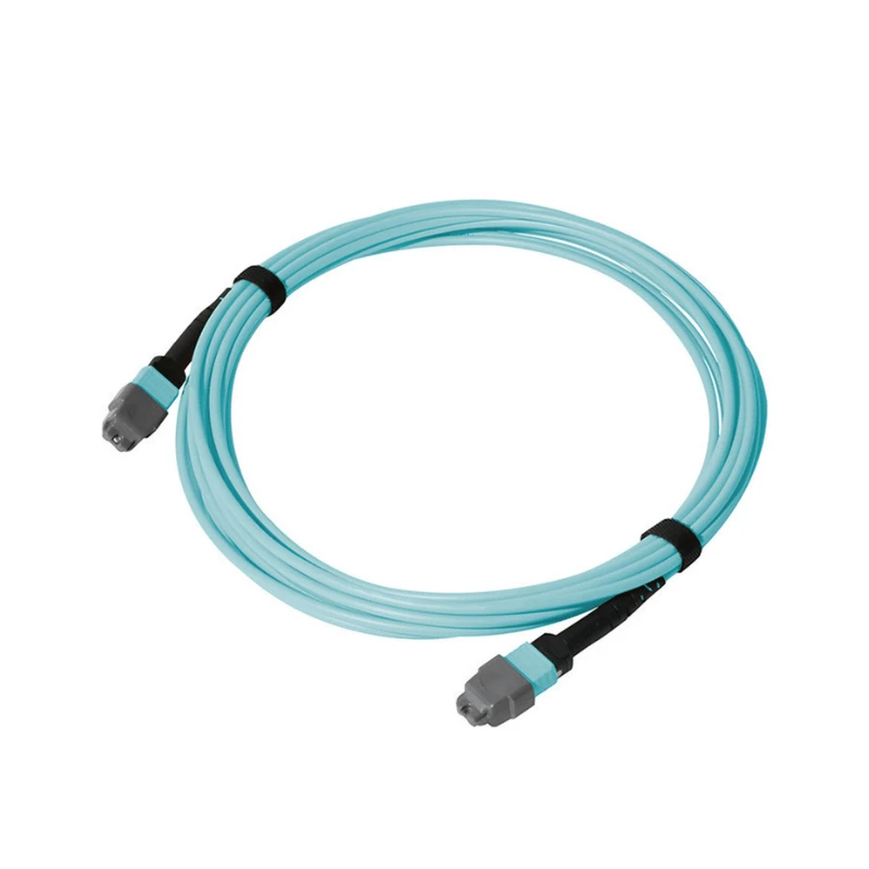
The MTP Loopback Cable is a factory-assembled multi-fiber optical assembly that provides a defined optical return path through an MTP/MPO interface. It routes transmitted optical channels back to designated receive channels within the same interface for transceiver verification, switch-port testing, equipment diagnostics, and optical test procedures.
Technical Specifications
|
Parameter |
Specification |
|
Product Type |
MTP Loopback Cable |
|
Connector Type |
MTP® / MPO |
|
Connector Gender |
MTP® Male (with guide pins) / Female (without guide pins) |
|
Fiber Count |
8 / 12 / 16 / 24 Fibers |
|
Fiber Type |
Multimode: OM3 / OM4 / OM5; Single-mode: OS2 |
|
Connector Polish |
PC / UPC / APC, according to fiber configuration |
|
Fiber Mapping |
Standard or Customer-Specified Tx-to-Rx Mapping |
|
Polarity |
Type A / Type B / Type C, where applicable |
|
Insertion Loss |
Standard Loss: ≤ 0.70 dB; Low Loss: ≤ 0.35 dB |
|
Return Loss |
According to fiber type, polish, and selected performance grade |
|
Attenuation |
Standard: 0 dB; Custom attenuation available |
|
Test Wavelength |
Multimode: 850 / 1300 nm; Single-mode: 1310 / 1550 nm |
|
Jacket Options |
PVC / LSZH / OFNR / OFNP, according to configuration |
|
Operating Temperature |
-20°C to +70°C |
|
Standards / Compliance |
IEC 61754-7; TIA-604-5; RoHS; REACH |
MTP Loopback Cable Interface Configuration
Specify the MTP loopback according to the target test interface. The required configuration should be confirmed before production based on the interface, connector mating, channel mapping, and optical test condition.
Match the Fiber Count to the Interface: Select the fiber count according to the active optical channels and connector configuration of the interface under test.
Match the Fiber Type to the Optical Interface: Match the fiber type to the optical mode specified for the target transceiver, equipment, or test fixture.
Confirm MTP/MPO Connector Gender: Confirm the required connector gender from the mating interface; male connectors are pinned, while female connectors are unpinned.
Confirm the Tx-to-Rx Mapping: Confirm the required Tx-to-Rx channel relationship before ordering, particularly for application-specific test configurations.
Check the Optical Test Condition: Confirm whether the test requires a direct or attenuated loopback and specify the required receive-power condition where applicable.
Tx-to-Rx Fiber Mapping
A loopback configuration is defined not only by fiber count, but also by how the transmitted channels are returned to the intended receive channels.
Standard Mapping
Standard configurations follow the confirmed fiber-position relationship for the specified MTP/MPO interface.
Custom Mapping
Customer-defined Tx-to-Rx routing can be reviewed from a fiber-position diagram, port map, or equipment specification.
Mapping Verification
The internal routing is checked against the confirmed production mapping before shipment.
Attenuation for Controlled Loopback Testing
Direct Loopback: A direct loopback returns the transmitted signal without intentional added attenuation when the resulting receive power meets the test requirement.
Attenuated Loopback: An attenuated configuration introduces a specified additional optical loss when the test requires lower receive power.
Attenuation Specification: Specify the required attenuation or target receiver condition so the optical configuration can be confirmed before production.
Factory Verification
MTP loopback assemblies are checked against the confirmed production specification before shipment, covering connector geometry, end-face condition, optical performance, and defined Tx-to-Rx routing.
Connector & End-Face Control: 3D interferometer inspection is used to check MTP/MPO connector geometry, including fiber height, apex offset, and radius of curvature, while connector end faces are inspected for contamination and visible defects.
Optical & Mapping Verification: Each assembly is individually tested for insertion loss and return loss according to the specified configuration and test wavelength, while defined Tx-to-Rx routing is checked against the confirmed production mapping.
Test Records: Serialized test records can be provided for individual assemblies, including applicable optical test data and inspection results for product qualification and incoming inspection.
Custom MTP Loopback Configuration
Custom MTP loopback cables are configured against the customer's equipment or test-fixture requirements.
Interface Reference
Provide the target equipment, transceiver, or test-fixture interface so the required connector and assembly configuration can be reviewed before production.
Mapping Reference
For non-standard loopbacks, provide a port map, fiber-position diagram, or Tx-to-Rx wiring specification.
Optical Requirement
Provide the required attenuation or target receiver condition when controlled optical power is part of the test specification.
Production Reference
Provide the required cable length, quantity, identification, and packaging requirements for quotation and production.
For application-specific configurations, DIMI reviews the supplied interface, mapping, and test requirements before production so the manufacturing specification can be confirmed against the requested assembly.
FAQ
Q: What is the difference between an MTP loopback cable and an MTP trunk cable?
A: An MTP trunk cable provides a multi-fiber connection between two network interfaces, while an MTP loopback cable creates an internal optical return path for testing a single interface.
Q: Can one MTP loopback cable be used with different transceiver configurations?
A: Not necessarily. Different transceiver interfaces can require different connector configurations, active fiber positions, channel assignments, and optical conditions, so the loopback should be matched to the specific interface being tested.
Q: Why can an MTP loopback with the correct fiber count still fail a port test?
A: Fiber count alone does not define the optical return path. An incorrect Tx-to-Rx relationship, connector configuration, or test condition can cause a failed result even when the fiber count matches.
Q: What can cause unexpected optical loss during an MTP loopback test?
A: Unexpected loss can result from connector end-face contamination, connector geometry, fiber damage, configuration mismatch, or measurement conditions. The test wavelength and measurement setup should also be checked when the measured loss is outside the expected range.
Q: Can I order an MTP loopback cable sample before placing a bulk order?
A: Yes. Engineering samples and initial trial orders can be arranged at lower quantities than the standard bulk MOQ, subject to the required configuration.
Q: What is the typical lead time for standard MTP loopback cable configurations?
A: Standard configurations can typically be completed in 3–7 working days. The final production schedule is confirmed according to order quantity and any non-standard requirements.
Q: Can DIMI provide test reports for MTP loopback cables?
A: Yes. Serialized test records can be provided for individual assemblies, with applicable insertion loss, return loss, and inspection data available for product qualification and incoming inspection.
Q: What is the MOQ for MTP loopback cables?
A: The standard bulk MOQ is 500 pieces per style, while engineering samples and initial trial orders can be arranged at lower quantities depending on the required configuration.
Hot Tags: MTP loopback cable, China MTP loopback cable manufacturers, suppliers, factory

