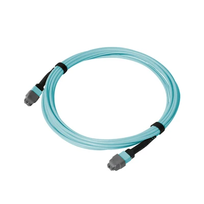


The MPO Single Mode Patch Cord is a factory-terminated multi-fiber optical assembly using OS2 single-mode fiber and MPO/MTP-compatible connector interfaces at both ends.
Technical Specifications
|
Parameter |
Specification |
|
Product Type |
MPO Single Mode Patch Cord |
|
Fiber Type |
OS2 Single Mode |
|
Fiber Standard |
G.652.D / G.657.A1 / G.657.A2 |
|
Connector Type |
MPO / MTP Compatible |
|
Connector Configuration |
MPO-to-MPO |
|
Connector Gender |
Male / Female |
|
Polarity |
Type A / Type B / Type C |
|
Polish |
UPC / APC |
|
Jacket Options |
LSZH / OFNP / OFNR / PVC |
|
Operating Temperature |
-20°C to +70°C |
|
Standards |
IEC 61754-7 / TIA-604-5 / RoHS / REACH |
|
Testing |
Insertion Loss, Return Loss, end-face inspection, 3D interferometry and polarity verification |
MPO-to-MPO Connection Configuration
Fiber Count
Specify 8F, 12F, 16F or 24F according to the fiber count required by the mating interfaces.
01
Connector Gender
Specify Male or Female according to the MPO interface installed on the mating equipment, adapter, cassette or cable assembly.
02
Pin Configuration
Confirm the pinned or non-pinned configuration required by the mating MPO interfaces.
03
Mating Configuration
Confirm the MPO interface at both ends against the equipment, adapter, cassette or cable assembly being connected.
04
Physical Compatibility
Confirm the connector gender and pin configuration against the mating interfaces before production.
05
Get the Polarity and Fiber Mapping Right
MPO polarity defines the fiber-position relationship between the two connector ends and must be selected according to the complete optical link.
Polarity Fiber Mapping
|
Polarity |
Fiber Mapping |
|
Type A |
Straight-through mapping |
|
Type B |
Reversed fiber mapping |
|
Type C |
Pair-flipped mapping |
Type A
Maintains the same fiber-position sequence between the two connector ends.
Type B
Reverses the fiber-position sequence between the two connector ends.
Type C
Reverses the fiber positions within each adjacent fiber pair.
System Matching
Select the polarity according to the existing cabling method and the interfaces connected at each end.
Fiber Mapping Verification
Confirm the required fiber mapping against the connected transceivers, MPO modules, cassettes, trunk assemblies or structured cabling before production.
For detailed MPO polarity selection and fiber-position mapping, refer to the Dimi MPO polarity guide.
Match the Optical Interface
Polish Type
Specify UPC or APC according to the mating interface and required return-loss specification.
Insertion Loss
Select Standard (≤0.35 dB) or Low Loss (≤0.25 dB) according to the optical link budget.
Return Loss
For APC configurations, the specified return loss is ≥60 dB.
Test Wavelength
Insertion loss and return loss are measured at 1310 nm and 1550 nm according to the specified test requirements.
Control the Physical Cable Configuration
Jacket Type
Choose LSZH, OFNP, OFNR or PVC according to the installation environment and applicable project requirements.
Cable Length
Specify the finished cable length according to the required routing distance between the two connection points.
Cable Construction
Confirm the required cable diameter and construction when the installation has defined space or routing constraints.
Pre-Shipment Verification
Dimi verifies the finished MPO assembly against the confirmed optical and connector configuration before shipment.
End-Face Inspection
Inspect MPO connector end faces for contamination and visible defects that could affect connector mating or optical performance.
3D Interferometry
Check MPO ferrule geometry using 3D interferometric measurement where specified for the connector assembly.
Insertion Loss
Measure insertion loss at the specified test wavelength against the confirmed loss grade.
Return Loss
Measure return loss at the specified test wavelength against the confirmed optical specification.
Polarity Verification
Verify the fiber mapping against the ordered Type A, Type B or Type C configuration.
Configuration Verification
Check the finished assembly against the confirmed fiber count, connector configuration, connector gender, polarity and other specified parameters before shipment.
FAQ
Q: What is an MPO single mode patch cord used for?
A: It provides a pre-terminated multi-fiber connection between MPO/MTP interfaces in single-mode optical cabling.
Q: What is the difference between MPO and MTP single mode patch cords?
A: MPO is the standardized multi-fiber connector interface, while MTP is a specific enhanced MPO connector design. Mating compatibility should be checked by connector configuration, gender, pin and polarity.
Q: Can an MPO single mode patch cord connect directly to an LC or SC interface?
A: No. An MPO-to-MPO patch cord has MPO interfaces at both ends. An MPO-to-LC or MPO-to-SC configuration is required when different connector interfaces are used.
Q: How do I specify an MPO patch cord for an existing fiber link?
A: Confirm the existing connector configuration, gender, pin arrangement, polarity and fiber mapping before selecting the patch cord.
Q: Can an MPO single mode patch cord be used for high-density fiber connections?
A: Yes. The MPO interface combines multiple single-mode fiber channels into one connectorized assembly for high-density cabling.
Q: What should be checked when replacing an existing MPO patch cord?
A: Match the existing fiber count, connector configuration, gender, pin arrangement, polarity, polish and optical requirements.
Q: What documentation can be provided with an MPO single mode patch cord order?
A: Depending on project requirements, documentation can include optical test results, polarity or fiber-mapping information and applicable compliance documents.
Q: What should be confirmed before ordering an MPO single mode patch cord?
A: Confirm the connector configuration, fiber count, gender, pin arrangement, polarity, polish, loss grade, jacket type and cable length against the mating system.
Hot Tags: MPO single mode patch cord, China MPO single mode patch cord manufacturers, suppliers, factory