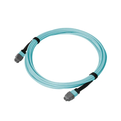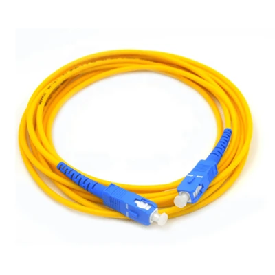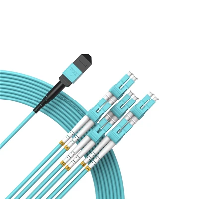


The MPO To LC Single Mode Fiber Cable is a factory-terminated OS2 breakout assembly that converts a multi-fiber MPO/MTP interface into individual LC duplex connections.
Technical Specifications
|
Parameter |
Specification |
|
Product Type |
MPO To LC Single Mode Fiber Cable |
|
Fiber Type |
OS2 Single Mode, 9/125 μm |
|
Fiber Grade |
G.652.D / G.657.A1 |
|
Fiber Count |
8 / 12 / 24 Fibers |
|
MPO Connector |
MPO/MTP Compatible, Male / Female |
|
MPO Polish |
UPC / APC |
|
LC Connector |
LC Duplex |
|
LC Polish |
UPC / APC |
|
Polarity |
Type A / Type B / Type C |
|
Insertion Loss |
Standard Loss ≤0.35 dB; Low Loss ≤0.20 dB |
|
Return Loss |
UPC ≥50 dB; APC ≥60 dB |
|
Cable Length |
Custom |
|
Breakout Length |
Custom |
|
Jacket Options |
LSZH / OFNP |
|
Operating Temperature |
-20°C to +70°C |
|
Optical Testing |
Insertion Loss / Return Loss |
|
Test Documentation |
Individual Optical Test Report |
|
Standard |
IEC 61300-3-35 |
MPO-to-LC Breakout Configuration
The cable uses a multi-fiber MPO/MTP interface on one side and separates the individual fibers through a breakout section into LC duplex connections on the other side.
The standard duplex relationship between the MPO fiber count and LC connections is:
|
MPO Fiber Count |
Standard LC Duplex Arrangement |
|
8 Fibers |
4 × LC Duplex |
|
12 Fibers |
6 × LC Duplex |
|
24 Fibers |
12 × LC Duplex |
The LC-side fiber arrangement is determined by the confirmed fiber mapping rather than by fiber count alone.
Configuration & Verification
Before production, the MPO-to-LC configuration should be checked against the mating interfaces and optical requirements of the intended link.
Connector Configuration
Specify MPO gender and polish according to the mating MPO interface. The LC side uses duplex connectors with the required UPC or APC polish.
Polarity & Fiber Mapping
Select Type A, Type B, or Type C according to the required fiber mapping and existing MPO connection scheme. If the required polarity is unclear, an existing cable specification or connection diagram can be provided for confirmation.
Optical Loss
Select the standard-loss or low-loss configuration according to the insertion-loss budget of the complete optical link.
Cable Dimensions
Confirm the overall cable length and breakout length according to the equipment layout and required LC connection position.
MPO-to-LC Assembly Manufacturing
Specification-Based Assembly
Each assembly is produced from the confirmed fiber count, connector configuration, polarity, fiber mapping, and cable dimensions, with the approved configuration used as the production reference.
MPO/MTP & LC Termination
The MPO/MTP and individual LC duplex connectors are factory-terminated according to the specified connector configuration and polish using controlled termination and inspection processes.
Controlled Breakout
The breakout section separates the fibers into the specified LC connections while maintaining the confirmed fiber arrangement through the assembly process.
Production Control
DIMI's fiber-optic assembly production is supported by dedicated optical testing and inspection equipment for connector and optical performance verification before shipment.
Testing & Inspection
100% Optical Testing
Each finished assembly undergoes insertion loss and return loss testing before shipment to verify optical performance against the specified requirements.
Connector End-Face Inspection
MPO/MTP and LC connector end faces are inspected for contamination, scratches, pits, and other conditions that may affect connector mating or optical performance.
3D Geometry Verification
Where specified for the connector configuration, interferometric inspection verifies connector end-face geometry, including fiber height, radius of curvature, and apex offset.
Test Documentation & Traceability
Individual optical test data can be provided for the delivered assembly, with the test record linked to the corresponding production identification where applicable.
Project-Specific Configuration
For quotation, buyers can provide the information required to define and verify the MPO-to-LC assembly:
Connection Details
MPO interface and connector gender
Fiber count
Polarity and fiber mapping
MPO and LC polish requirements
Physical Details
Overall cable length
Breakout length
Jacket requirement
Order Details
Required quantity
Labeling or identification requirements
Packaging requirements
When the polarity or fiber mapping is unclear, an existing cable specification, connection diagram, mating interface, or equipment information can be provided for configuration review before production.
For repeat orders, a previously approved production specification can be referenced to maintain the same confirmed configuration when project requirements remain unchanged.
FAQ
Q: What is the difference between an MPO to LC breakout cable and an MPO trunk cable?
A: An MPO to LC breakout cable converts a multi-fiber MPO/MTP interface into individual LC duplex connections, while an MPO trunk cable maintains MPO/MTP connections at both ends for multi-fiber interconnection.
Q: What is the difference between MPO and MTP for an MPO to LC cable?
A: MPO is the standardized multi-fiber connector interface, while MTP is a higher-performance connector design based on the MPO interface. The required connector configuration should be matched to the mating interface specified for the installation.
Q: How should an MPO to LC cable be selected for a replacement installation?
A: Match the replacement cable to the existing fiber count, MPO interface, connector gender, polarity, fiber mapping, LC configuration, cable dimensions, and optical requirements before ordering.
Q: How does an MPO to LC cable affect the optical link budget?
A: The assembly adds connector and termination loss to the optical link, so its specified or measured insertion loss should be included when calculating the available system loss margin.
Q: What bend radius should be considered for an MPO to LC breakout cable?
A: The minimum bend radius should be confirmed from the selected cable construction and considered for both the main cable section and the breakout area when routing the assembly through restricted spaces.
Q: What test documentation is provided with an MPO to LC single mode fiber cable?
A: Individual optical test data for the delivered assembly can be provided, including measured insertion loss and return loss results for review against the specified requirements.
Q: What is the MOQ for MPO to LC Single Mode Fiber Cable?
A: The standard MOQ is 500 pieces per configuration, with the final quantity confirmed according to the required fiber count, connector configuration, and project requirements.
Q: What is the lead time for MPO to LC Single Mode Fiber Cable?
A: Samples can generally be completed in 3–5 working days, while bulk production typically requires 15–30 working days, depending on the confirmed configuration and order quantity.
Hot Tags: MPO to lc single mode fiber cable, China MPO to lc single mode fiber cable manufacturers, suppliers, factory